Eye Pattern
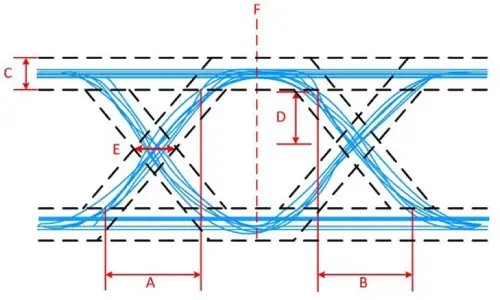
B. Fall time in the diagram is the mean of the individual fall times. The slope indicates sensitivity to timing error; the smaller the better. C. The width of the logic high value is the amount of distortion in the signal (set by the signal-to-noise ratio). D. The signal-to-noise ratio at the sampling point is from the eye width to the bottom or the logic high-voltage range. E. Jitter of the signal. F. The most open part of the eye is when there is the best signal-to-noise ratio and is thus the best time to sample.

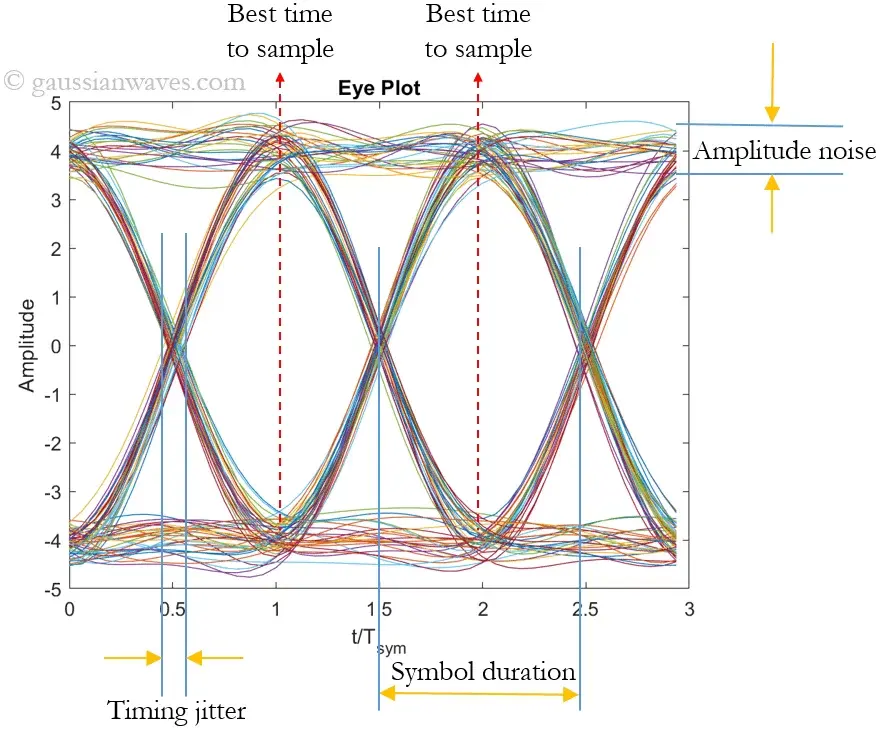
Eye diagram is a powerful tool to analyze the overall quality of a communication link. It reveals important characteristics of a communication link, that includes timing sensitivity, noise margin, ISI (Inter-Symbol Interference) and zero-crossing jitter. It also shows the optimum sampling time for the receiver, which indicates when to sample the incoming signal for converting it to a symbol stream. It is more useful to plot the eye diagram at the receiver, where it gives visual cues for the engineers to check the signal integrity and to uncover problems in earlier stages of the design process.
From a mathematical perspective, an eye pattern is a visualization of the probability density function (PDF) of the signal, modulo the unit interval (UI). In other words, it shows the probability of the signal being at each possible voltage across the duration of the UI. Typically a color ramp is applied to the PDF in order to make small brightness differences easier to visualize.
| Eye-diagram feature | What is measures |
|---|---|
| Eye closure | Intersymbol interference, additive noise |
| Eye opening (height, peak to peak) | Additive noise in the signal |
| Eye overshoot/undershoot | distortion due to interruptions in the signal path |
| Eye width | Timing synchronization & jitter effects |
Ideal eye
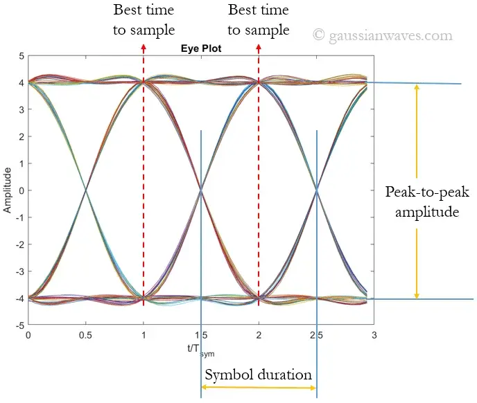
An ideal eye diagram will show a wider eye that has a lot of margin in both horizontal and vertical direction that allows for lowest possible error rate in the receiver decisions.
Below: 2-PAM modulated square-root raised cosine (β=1) pulse shaped symbols sent through an AWGN channel having EbN0=50 dB (almost no noise condition).
Narrower eye
A narrower eye implies increased sensitivity to noise, since presence of more noise would cause erroneous symbol decisions. In essence, erroneous symbol decisions could be caused by timing jitters (measured in the horizontal direction) or the amplitude variation (measured in the vertical direction) or intersymbol interference (which affects the signal in both directions)
Below: 2-PAM modulated symbols sent through an AWGN channel having EbN0=20 dB (signal to noise ratio).