Digital Communication Block Diagram
Table of contents
- Introduction
- Source Encoder
- Channel Encoder
- Digital Modulator
- Channel
- Digital Demodulator
- Channel Decoder
- Source Decoder
- Output Transducer
- Output Signal
- FM — Frequency Modulation
- PCM — Pulse Code Modulation
- Low Pass Filter
- Sampler
- Quantizer
- Encoder
- Regenerative Repeater
- Decoder
- Reconstruction Filter
- Broadband, wideband and narrowband
- USRP (Universal Software Radio Peripheral)
- References
Introduction
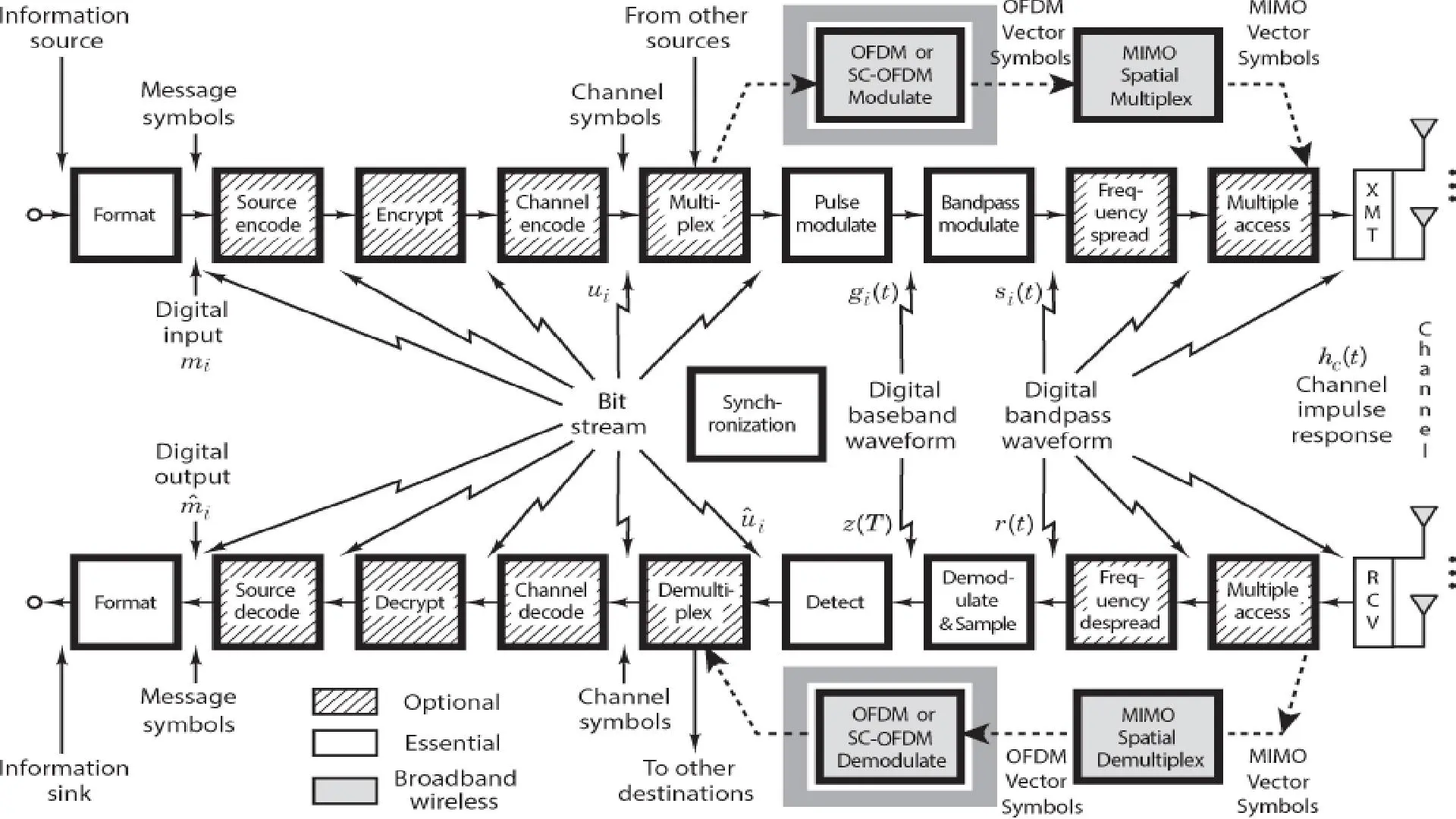
Source Encoder
The source encoder compresses the data into minimum number of bits. This process helps in effective utilization of the bandwidth. It removes the redundant bits unnecessary excess bits, i.e., zeroes.
Channel Encoder
The channel encoder, does the coding for error correction. During the transmission of the signal, due to the noise in the channel, the signal may get altered and hence to avoid this, the channel encoder adds some redundant bits to the transmitted data. These are the error correcting bits.
Digital Modulator
The signal to be transmitted is modulated here by a carrier. The signal is also converted to analog from the digital sequence, in order to make it travel through the channel or medium.
Channel
The channel or a medium, allows the analog signal to transmit from the transmitter end to the receiver end.
Digital Demodulator
This is the first step at the receiver end. The received signal is demodulated as well as converted again from analog to digital. The signal gets reconstructed here.
Channel Decoder
The channel decoder, after detecting the sequence, does some error corrections. The distortions which might occur during the transmission, are corrected by adding some redundant bits. This addition of bits helps in the complete recovery of the original signal.
Source Decoder
The resultant signal is once again digitized by sampling and quantizing so that the pure digital output is obtained without the loss of information. The source decoder recreates the source output.
Output Transducer
This is the last block which converts the signal into the original physical form, which was at the input of the transmitter. It converts the electrical signal into physical output (Example: loud speaker).
Output Signal
This is the output which is produced after the whole process. Example − The sound signal received.
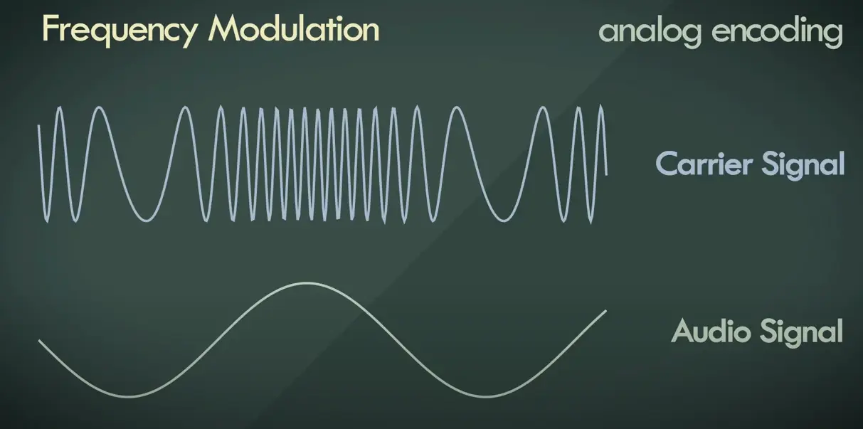
FM — Frequency Modulation
- High frequency = high energy
- Less power required for transmission
- Unaffected by interference/noise
PCM — Pulse Code Modulation
- Commonly used
- Easy to understand
- Antecedent to all other methods
- Lossless encoding
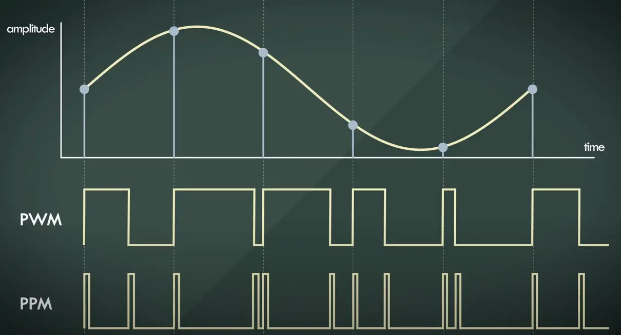
Instead of a pulse train, PCM produces a series of numbers or digits, and hence this process is called as digital.
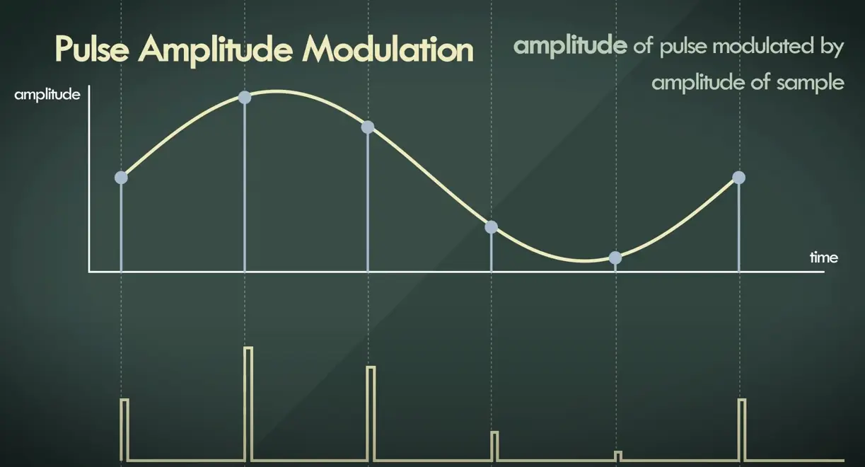
Each one of these digits, though in binary code, represent the approximate amplitude of the signal sample at that instant.
In Pulse Code Modulation, the message signal is represented by a sequence of coded pulses. This message signal is achieved by representing the signal in discrete form in both time and amplitude.
PCM Encoding
- Companding PCM
- Differential PCM
- Adaptive Differential PCM
- Linear Predictive PCM
- Delta Modulation
- Modified Discrete Cosine Transform
Basic Elements of PCM
Low Pass Filter
This filter eliminates the high frequency components present in the input analog signal which is greater than the highest frequency of the message signal, to avoid aliasing of the message signal.
Sampler
- p.e. 44.1kHz at 1 second
This is the technique which helps to collect the sample data at instantaneous values of message signal, so as to reconstruct the original signal. The sampling rate must be greater than twice the highest frequency component W of the message signal, in accordance with the sampling theorem.
The typical human speech is represented by a simple 1200 Hz tone, which is represented by a sine wave.
If a and-limited signal is sampled at regular intervals of time and at a rate equal to or higher than twice (2x) the highest significant signal frequency, then the sample contains all the information of the original signal.
The original signal may then be reconstructed by use of a low-pass filter.
Based on Nyquist sampling theorem, we can derive that the nominal 4 kHz voice channel can be reconstructed by a sampling rate of 8000 times per second (4000 x 2).
This means that a sample is taken every 125 μsec, or 1 second/8000.
Quantizer
- p.e. 16bits (65.536 levels)
Quantizing is a process of reducing the excessive bits and confining the data. The sampled output when given to Quantizer, reduces the redundant bits and compresses the value.
The exact sample value is replaced by the closest value allowed. The infinite number of levels is transformed into a finite number of levels.
- p.e. 44.1k samples x 16bits = 705.6kbps for a single audio channel
- sample rate x bit depth x number of channels = bandwidth of multichannel audio
Encoder
- The digitization of analog signal is done by the encoder.
- It designates each quantized level by a binary code.
- The sampling done here is the sample-and-hold process.
- Encoding minimizes the bandwidth used.
Regenerative Repeater
This section increases the signal strength. The output of the channel also has one regenerative repeater circuit, to compensate the signal loss and reconstruct the signal, and also to increase its strength.
Decoder
The decoder circuit decodes the pulse coded waveform to reproduce the original signal. This circuit acts as the demodulator.
Reconstruction Filter
After the digital-to-analog conversion is done by the regenerative circuit and the decoder, a low-pass filter is employed, called as the reconstruction filter to get back the original signal.
Hence, the Pulse Code Modulator circuit digitizes the given analog signal, codes it and samples it, and then transmits it in an analog form. This whole process is repeated in a reverse pattern to obtain the original signal.
Broadband, wideband and narrowband
USRP (Universal Software Radio Peripheral)
References
- Digital Communication - Quick Guide
- Lecture 11, ELG3175: Introduction to Communication Systems
- Stanford Lecture 13: Pulse Code Modulation
- WHAT IS PULSE CODE MODULATION (PCM)?
- Video 10. Pulse Code Modulation - Digital Audio Fundamentals
- Video Digital Show & Tell
- Video A Digital Media Primer for Geeks